


As seen on TV! MeArm on the Gadget Show (UK)
Quite shocking that it’s been three months since the last project update on hackaday.io! So much has been going on with the #meArm project and the business that created it (well it was me (Ben) but for phenoptix, which was also me).
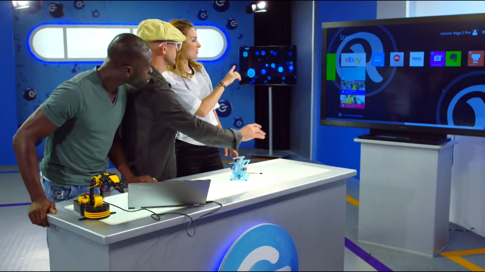
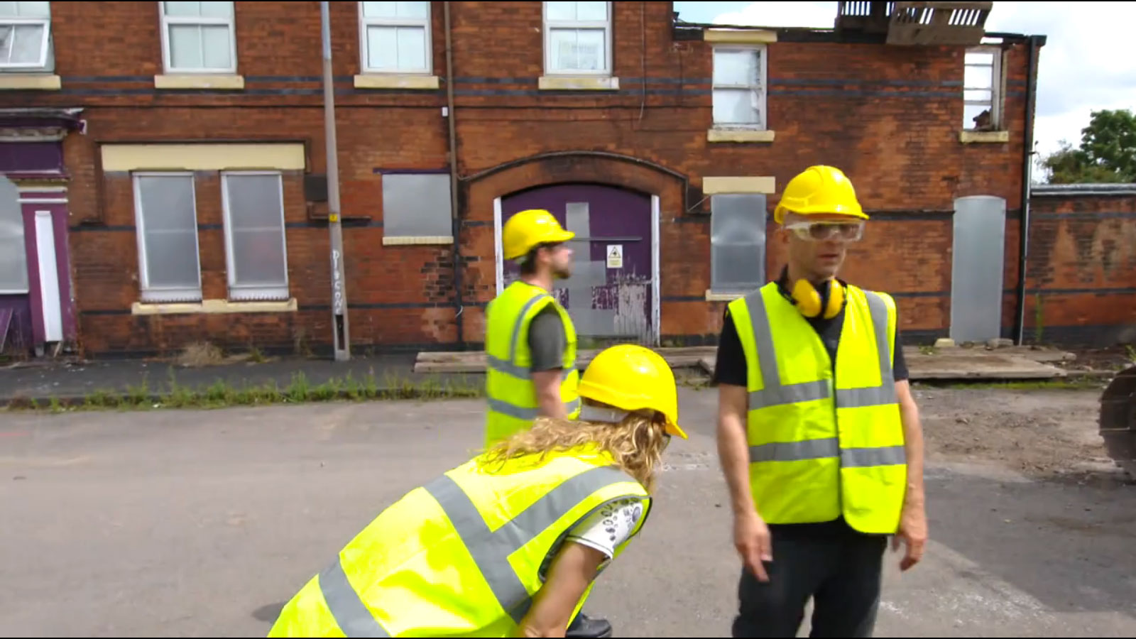
The super secret project that the #meArm maxi was built for was for a TV show in the UK where they wanted to knock down a building using a digger controlled via a robot arm. Unfortunately I had very little hands on time with the machine we used and just sent the maxi down for testing. A couple of issues meant the maxi was under powered and ultimately left out of contention. I did manage to accompany Shay who’s company Running in the halls (RITH) did all of the software work for the piece during filming and help cobble together the Mechano solution. This meant the #meArm was part of the story and did at least get used as a prop during filming! I did even get a one second cameo myself! I’m the blurry guy with the beard in the background
Just when I thought I was out....
Wow so it’s been an amazing few weeks. It was great to start at Ciseco and get to know them and their fantastic products a little better. However last Monday I made a very hard decision and decided to take another leap into the unknown with the #meArm. Joining forces with Des19nCore we have formed MeArm limited to make the most of the potential that the little robot from phenoptix has. As stated in my reasons for the changes at phenoptix this should still give be the flexibility to have more family time!
In just eight months it’s gone from a paper model to a slick and handsome pocket size robot with software support for the Arduino, Raspberry Pi, Beaglebone Black, Spark Core and Espruino! We’ve seen work shops spring up around the world and we have distributors and manufacturers in the four corners of the globe!
Our first challenge is to satisfy the demand that we already have and this week we’ll be setting up a new production line.
Read moreTaiwanese
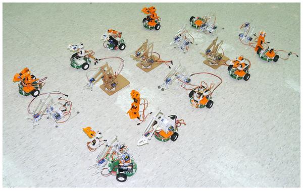
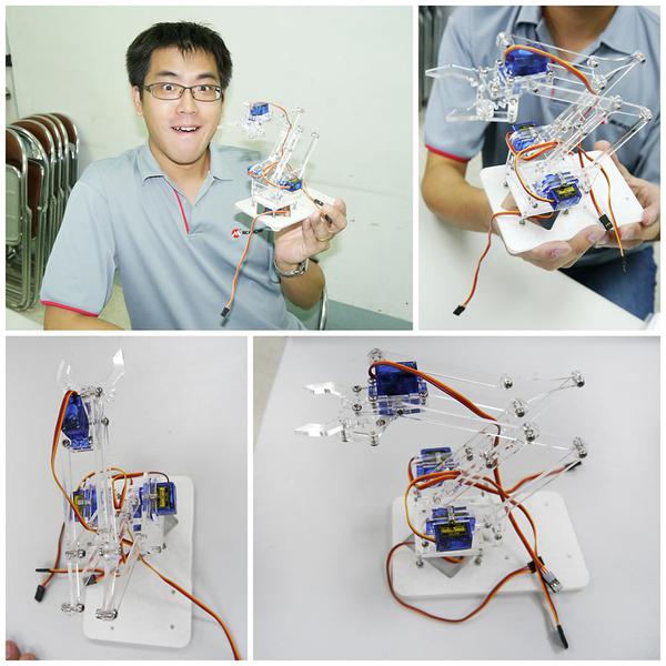
Had a new make on thingiverse this morning, which linked onto an amazing blog.
This was the image that caught my eye - they’ve made a #meArm Army! Would love to know more about the base robot so if anyone knows get in touch at ben at phenoptix dot com.
There are loads more images on the blog, with lots of people posing with their #meArm and this great group shot
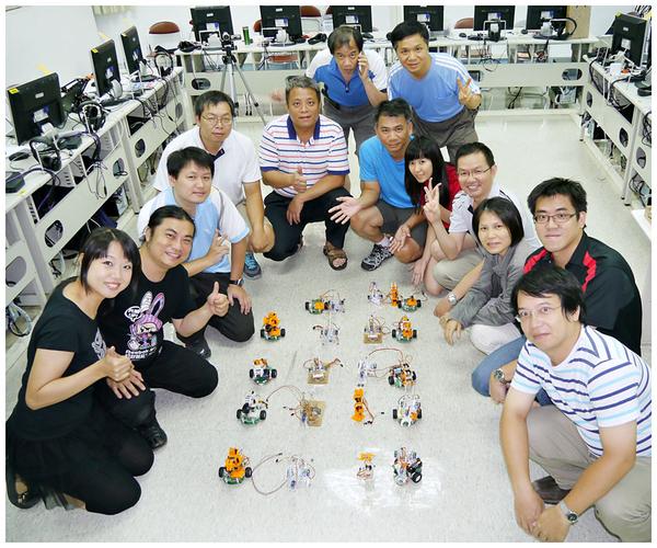
They’ve added a link to our thingiverse objected and mentioned the #meArm project. It is so exciting to see the #meArm being used for what it is meant to be used for - fun and education! This guy sums up how I feel about finding this post
Early Bird Update
Yesterday I shipped 30 Mirobots to the Early Bird backers from Kickstarter. These units have quite a few improvements that have been based on the feedback from the beta testers as well as my experiences in sending out the beta units.

PCB improvements
The main change on this version is a much simplified PCB. This was brought about by using an Arduino Pro Mini which runs at 3.3V instead of the previous 5V. Running at a lower voltage has a couple of advantages; it means that we can talk to the WiFi module (which is also at 3.3V) without needing any resistors to convert between voltages and very importantly, it also means that we can run from 4 AA batteries instead of the previous 5. If you’ve ever bought a battery charger or any packs of batteries, you’ll know that they don’t tend to come in packs of 5. This should make using it on a regular basis (e.g. in a classroom) much easier because you can just use a 4 battery charger.

One of the other big changes that I’m happy about is that I used a PCB mounted battery pack which does away with the wire that ran from the battery pack to the PCB. This was a pain because these packs tend to come with bare wires, but crimping is beyond what people should have to do during assembly, so I was either going to have to hand crimp these cables or get them done at a factory which would be expensive. It also means that the battery pack is held in place nice and securely just because it is attached to the PCB.
One of the most requested features was a power switch, which I’m pleased to announce Mirobot now has! It’s much more reliable than having to pull the power cable out.
Another simplification is the driver chip. Previously I was using two 7 channel ULN2003 driver chips, primarily because these came free with the stepper motor I was using so they were the quickest thing to use. I’ve switched to the 8 channel ULN2803 which means it can handle both stepper motors.
You can compare the instructions for the previous version to this new version to see how much simpler the build process has become (you should also notice improvements in the instructions).
Pen arm improvements
The chassis design has been quite stable for a while now, however one of the outstanding issues that’s always bothered me was that unless the pen was adjusted perfectly there could be too much pressure on the pen arm which meant that the wheels began to spin. There were two possible approaches to this solution; either give the wheels more grip or reduce the pen arm friction. I opted for the latter because all of the solutions I could come up with for improving the wheel grip made the chassis assembly much more complex which goes against the main design goal of it being built by children.

The elastic band pulling the arm down was the main culprit but I’d always thought this was needed to keep the arm in place as well as provide pressure downwards. I managed to design an arm which holds itself in place without the elastic band and so now the only pressure is the weight of the pen and arm. Being able to get rid of one of the more fiddly parts of the assembly is a very nice side effect. It does mean that it works best with pens that don’t require lots of pressure (e.g. felt tips rather than ball point pens) but that was always the case really.
Packaging upgrade
For the beta units my main concern was in getting the design and software finalised enough to be able to send them out for testing. The packaging was a bit of an afterthought and to be honest, it felt that way. I wrote about the new packaging in a previous post and I’m really happy with how it turned out.

There are some big benefits:
- A number of beta testers had either missing or broken chassis parts - it would be very difficult to damage these now and there’s no way of packaging it up without any of the parts.
- The laser cut parts need cleaning once they come off the machine. By cutting out the parts fully it means they all have to be cleaned separately. Leaving them in a panel means it’s possible now to just rub a cloth over the whole thing and it’s much, much quicker.
- Because all of the larger pieces of the kit fit nicely into the assembly it stands out a mile away if any are missing.
What’s next?
There are a few things left for me to do before shipping out the bulk of the units to my Kickstarter backers:
- I need to finalise the addons. I’ve done some work in thinking about how they can be built and planned ahead so hopefully thy’ll be backwards compatible.
- Put a cover around the package. At the moment it goes straight into the cardboard packaging which means if you want to use it as a gift it doesn’t work so well once it’s removed. It need to stand alone without the cardboard I think.
- The pegs need to be more manufacturable. At the moment they are all cut out of a sheet of acrylic individually (they tessalate so it’s quite quick) but this means they all need counting out to go in the bag. I’d like to take a similar approach to the chassis and have them come out in groups of 12 (you get some spares) held together by tabs.
That’s all for now. I’m about to go on holiday for a couple of weeks but after that it’s full tilt towards getting the main batch of units out for Kickstarter.
Read more