Arduinobot is now Mirobot
The project is still very much alive. After a hiatus of almost two years it’s great to be posting something here again.
The first news is that I’ve changed the name of the project. Arduinobot was a bad name because it piggy-backed on the Arduino brand (which is a bad thing to do) so I’ve renamed it to Mirobot. There are a few things behind the name but essentially it came from thinking about what an artistic drawing robot might be called. It’s named after Joan Miró, the 20th Century Spanish artist.
Since I left Xively I’ve been dedicating several days a week to completing the first version of Mirobot. This was the main reason for the hiatus - it was too difficult to do work on hardware without a good workshop. Setting up on the kitchen table is far from ideal so now I’ve got a proper workshop (with room for a laser cutter :-) I’ve made much better progress. Some of the things I’ve done in the last couple of months are:
- Re-worked the drive train to use direct-drive geared steppers. This massively simplifies the mechanical design as well as being even lower cost
- Designed a custom circuit board that fits nicely in the robot and that’s very low cost to build. It’s all through-hole so it can be easily soldered. More on that later.
- Set up a WiFi module so it’s completely wireless and networkable.
- Written a couple of Arduino libraries;
- HotStepper is a lightweight interrupt driven stepper motor driver
- LogoVM is a customisable virtual machine that runs the LOGO language for telling it what to do
The aims of the project are unchanged; create a low cost, fully open source drawing robot that can be used to teach children about technology and programming.
There are lots of plans for building the supporting parts of the project like the documentation and instructions as well as a web site where people can learn, but more about those in the future. I’m going to be selling Mirobots as kits to try and get lots out into the world. Sign up to the mailing list using the form below if you’d like to be notified when they are available.
Read moreOpenSCAD
It’s been a pretty busy Christmas period having moved house (again) but I’ve been making some more progress on the chassis. One of the things that has been bugging me with my current system based on Illustrator is that it is so difficult to make small changes (e.g. the material thickness) because you have to manually go and tweak all of the dimensions of all of the slots and holes to compensate. So on my normal rounds of exploring makers on the web I came across this smart bottle carrier which mentioned that it was built in OpenSCAD which allows you to make parametric changes to the design to adjust it for things like this. 
A few days later and I’ve been making steady progress on getting my design into this awesome program. It’s pretty basic, but extremely powerful, especially if you can program. Some things take a very long amount of time (e.g. trying to do any curved edges!) but others, especially those that are simple repeating elements or geometrical operations can be defined easily in code are very quick.
One of the nice things about this program is that it should make it easier when I open the designs because if someone wants to cut it themselves but only has 4mm ply, they should be able to just adjust the material thickness constant to suit. It should then be possible to just export as a DXF and start cutting.
For some reason, I also find it to be an extremely satisfying process and have been enjoying it massively.
Read morePen arm working
Here’s a quick demo of the pen arm in action:
I’m pretty happy with how it’s working. Now I just need to get the drive train working. I think a few things are conspiring against it at the moment:
- Underpowered steppers - I’m intentionally using smaller steppers to keep the cost down, but powering these from 5V USB means they haven’t got much power. I’m going to use a 12V battery pack to get a bit more out of them.
- Drag from the USB cable - the only USB cable I have is pretty stiff so puts quite a lot of drag on the bot. I’ve got a bluetooth module I’m going to use which, in combination with the battery pack, should cut this out of the equation.
- Lack of grip on the wheels - I tried running an elastic band around the main wheel which did work a bit, but quickly slipped off and made things worse.
- Not 100% sure I’m driving the steppers correctly so I need to double check that too.
Now I just need to find the time to sit down and dig into it.
Read moreChassis v2
I got the second version of the chassis back from skpang yesterday and managed to quickly assemble it late last night to see how it is looking. Here’s a photo of it next to the v1 chassis: 
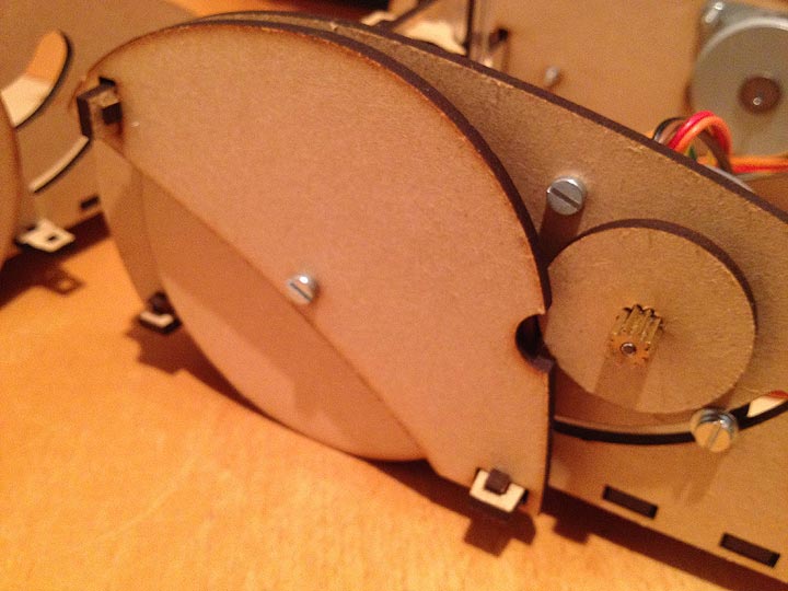
It’s virtually the same design but has a few refinements. This time you can see the “mudguards” which aren’t really mudguards but more like plates that hold the outer end of the axle in place. They seem to work quite well as the wheels are much less wobbly than on the v1 chassis. You can also see the drive wheel that fits on the gear of the stepper motor. Although this is looser than expected it gets held in place quite nicely by the mudguards. There are three of these in different sizes which should give a resolution of 0.5mm, 1mm and 2mm depending on whether you want speed or accuracy. Here’s a close-up:

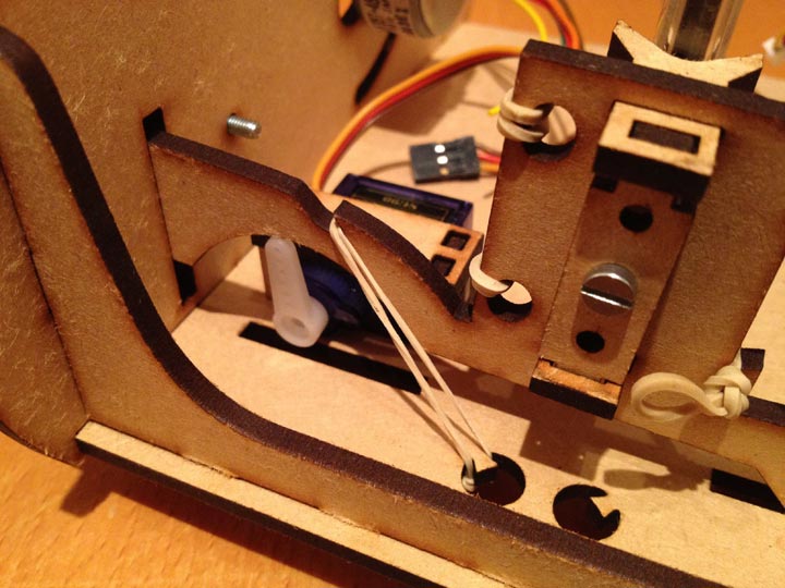
The other major refinements in this version were the attachments for the rubber band to keep the pen arm in place. I’m really pleased with how this is working; there’s very little play and the tension holds the hinge in place really nicely. Here’s a close-up of this part:

The main area for improvement, however, is the mount that holds the servo in place that raises and lowers this arm. I’d hoped to rely on friction to keep this held tight, but I think with the tolerances of the laser cutter it’s going to be quite difficult to make this a reliable fit, especially with the elastic levering the arm against it in the opposite direction. Plus, if it gets taken apart and putt ogether again a few times this will likely become loose. Since the elastic bands are working so well elsewhere I’m considering designs based on one keeping it tightly in place, but it also needs to be quite accurately aligned with the arm otherwise it will slip off.
In any case, I should at least be able to get this version moving properly before spinning another revision of the chassis so I’ll hopefully be able to put up some video before too long. Expect the ususal quips about number 5 (or 2) being alive.
Read more

