Chassis v1
Despite the lack of activity on this development blog I haven’t been completely idle. On the train whilst commuting to work I’ve been working on the chassis design. The other day I got back the first version and managed to get it mostly assembled to see what works and what doesn’t. It’s not looking too bad. Apart from a couple of missing holes which meant I couldn’t fit the plates that hold the outer end of the wheel axle it mostly fits together OK. Of course I had to do a bit of whittling because I’d designed for 3mm MDF, but the board I used turned out to be 3.3mm (I’ve since bought myself a shiny new pair of digital calipers - like I needed an excuse). Also, I mis-measured the size of the gear on the stepper so the gear wheel that fits on to it doesn’t fit either. I’m using old-school pegs to keep it all together to avoid the use of any more additional components like screws. Apart from the steppers and other electronics, the only components that aren’t laser cut are 7 screws, 4 nuts, 6 washers, 5 elastic bands and a ball-bearing caster wheel (that I’m hoping to eliminate in a future iteration. Still pretty cheap.
Here are a few photos of the assembled chassis. This is an overall view of the chassis:

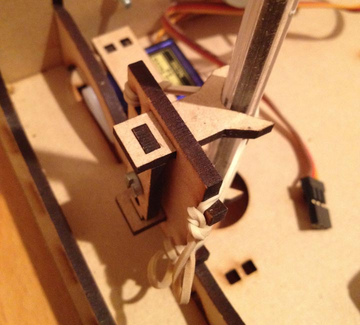
Here’s a close up of the pen arm:

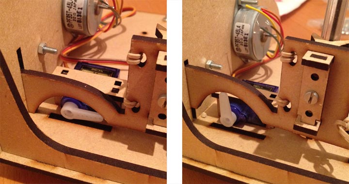
I’m particularly pleased with this part as it only requires one extra part (a screw) to function. Pressure is maintained through the use of elastic bands (which aren’t fitted to this version) and the pen is also held tight by a couple of elastic bands. It sits into a couple of slots on either side of the chassis to keep it nice and rigid and the hinge is made by sitting a 110° corner against a 90° one and using the angle of the elastic band to hold it in place. You can see how this is raised and lowered using a servo in this next picture:

Here’s a close up of the motor being kept pressured against the wheel:

I’m thinking about thinly spreading some rubbery glue on the outer edge of the main wheel which will both grip the floor surface as well as providing grip against this wheel, alternatively another elastic band stretched around it may work well (or it may just keep coming off).
I’m hoping that the next iteration (which I’ve sent off to Sukkin at skpang.co.uk for laser cutting) will assemble without to omany tweaks and I might actually be able to get the whole thing powered up and moving.
Read moreStarting Construction
This is the second of two posts today about the progress I made building the first early stage prototype of the Arduinobot. My main aim with this physical prototype was to test out the drive train mechanism to see if it was going to work. I’d had an idea that by driving the edge of the wheel I’d be able to use a smaller, cheaper, lower resolution stepper motor. One of my prime aims is to make this kit as cheap as possible and this means that I can use a £4 motor instead of an £8 one - it also means that I don’t have to buy the expensive mounting kits for attaching the motor shaft to the wheels (e.g. this one). My main concern about this method is that the stepper will either be too slow or too underpowered to work properly. Although this was just a cardboard prototype, it did bring a few things to light.
Speed
My initial tests were getting 300 rpm out of the motor, but these were at 7.5V. When I used a 5V USB supply, I found that I was only getting about 150 - 200 rpm. Also, one of my motors was faulty so I replaced it with a very similar one I salvaged from a printer years ago. Unfortunately, this motor would only run at 100 rpm, so the speed of this test was extremely hampered. Theoretically, given that the gear that’s driving the wheel is 6.4mm in diameter, and so has a circumference of approx. 20mm. 300 rpm means it will move at around 6 meters per minute which should be adequate.
Grip
A thin cardboard wheel doesn’t have a whole lot of grip, but this test made me realise that I might need to add some kind of rubberised edge to the wheels (which I’m planning to laser cut out of ply). I’m considering routing a thin groove around the edge of the wheel and stretching an elastic band around it to provide good grip, both at the drive gear and the ground. I’m also considering using a slightly thicker grade of ply to give more surface area to the ground.
Axles
The cardboard construction had way too much flex in it to work properly, but it demonstrated that if there is any pressure against the axle it will need to be very securely attached so as not to skew the angle of the wheels. I think this should be fine once I’m using laser-cut ply. The problem was that the cardboard quickly developed a lot of play in the joints. I went for two seperate axles rather than one that goes the whole width because this would get in the way of the pen which has to go at the central point between the two wheels.
Third wheel
I ended up using some Lego as the third wheel for this prototype, but I realised that I’m going to have to give this a decent amount of thought. It needs to have full 360 degree movement and to have minimal drag. There are quite a few products on the market but the prices range from $8.75 for an Omni Caster Wheel to $2.99 ($for a Ball Caster. I’m trying to think if there is a way of making this part using the same technique as the rest of the chassis, but I’ll have to get into the design in more detail first.
Pen mechanism
This feature complicates the overall design considerably; it has to go directly between the two wheels, and it will probably take up the main flat area of the chassis, so the Arduino will probably need to sit on a layer above. It’s a crucial feature though, and in itself will be quite tricky to get right, especially if the cost is kept down. I’ll probably do this with a servo initially, but I’m looking for a cheaper alternative for the final design.
I need to get up to speed on using the laser cutter to do some more prototyping and spend some serious time in the London Hackspace because cardboard just doesn’t cut it! I’m very used to using Illustrator, but unfortunately don’t have a copy so I’m going to have to figure out how to use something like Inkscape or SketchUp to create the files for the laser cutter.
Read moreCommand and Control
I spent today hacking at a couple of things on the Arduinobot; a Logo based command set based on the original Turtle Logo and making a prototype chassis. This post is about the Logo command set and another will follow with what I learned from the prototype.
I found a very small example of some original BBC Turtle Logo programming here and then came across some pretty good documentation along with some interactive examples here. I also found this awesome wiki by Cynthia Solomon, one of the original developers of Logo - check out the footage of the BBC turtle in some of the Youtube clips. I’d be fascinated to see some more original examples of the original BBC Turtle Logo as I’m unsure exactly which features it supports. Turtle Logo seems to be a subset of Logo and from my research it looks like there are a few levels of commands which get increasingly complex:
Basic commands:
- FD
- move forward by \ mm - BK
- move backward by \ mm - RT
- rotate clockwise by \ degrees - RT
- rotate anti-clockwise by \ degrees - PU - move the pen up (i.e. stop drawing)
- PU - move the pen down (i.e. start drawing)
Iterative commands:
- REPEAT <count> [<commands>] - repeats the commands within the brackets <count> times. The commands look like they each accept one argument only and can be just written after eachother, e.g. REPEAT 10 [FD 100 RT 30]
Procedural commands:
- TO - allows the user to define procedures and pass them arguments.
My plan of action is to tackle the language in this order - I’ve already got the basic commands working well (although they aren’t calibrated yet). I think the REPEAT statement is a crucial part of the Turtle experience and is much easier to fit into the line oriented processing that I currently have working. At the moment I’m taking the approach of processing each line as it comes in and performing the action that the command specified. To support adding functions at run time will be a nice interesting challenge, but one that should fit into the framework I’ve developed quite well.
I’ve still got a few questions about Logo - it seems like there are quite a few variants so I’m not sure what should be in scope for this project. If anyone can help with these qustions it would be much appreciated.
- Can a function have more than one argument?
- If so, when it is in a repeat statement, how does it look?
- Can repeat statements be on multiple lines?
I’m planning on turning this into a proper arduino library, but at the moment here’s the arduino sketch that has everything in it. It’s pretty straightforward (except the bit about passing function references) and there’s some room for improvement, but it seems to be working well.
Read moreSome progress
It took quite a while for the kit I ordered from Adafruit to arrive - and of course when it did it sat in the post office for a while waiting for me to find the time to go and pay the £15 customs charge (of which £8 was paid for the privilege of the Royal Mail handling it at all). Anyway, I spent some time at the weekend with my 4 year old son, Euan, soldering the stepper driver board together (he mainly enjoyed snipping the solder) so I’m now at the point of trying to get the motors going.
I’m also planning on joining the London Hackspace so that I can make use of their nice new (ish) laser cutter - I’ll keep you posted.
Read more

