Chassis Evolution
The chassis for Mirobot has changed quite a bit since I first started designing it. It’s now at a point where it actually works and I feel a lot more confident about using it with people other than myself. I’ve got two sets of the new one ready to be boxed up for Christmas for my kids now which was my driver for building it in the first place. We’ll have some fun soldering over Christmas. I was looking through the old chassis designs and thought it would be interesting to trace the design evolution from the first stages, where it just didn’t work, to now where it does. The changes are relatively minor but have had a massive impact on functionality.
Version 1
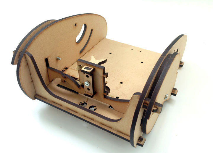
This was the first iteration and it performed horribly. The wheels were screwed on and driven from the edge by a stepper with a drive wheel but didn’t move very freely. The problems with this version were that the drive train didn’t really work at all and the servo wasn’t held down well and came loose. The pen arm worked well first time so long as the servo was held in place.
Version 2
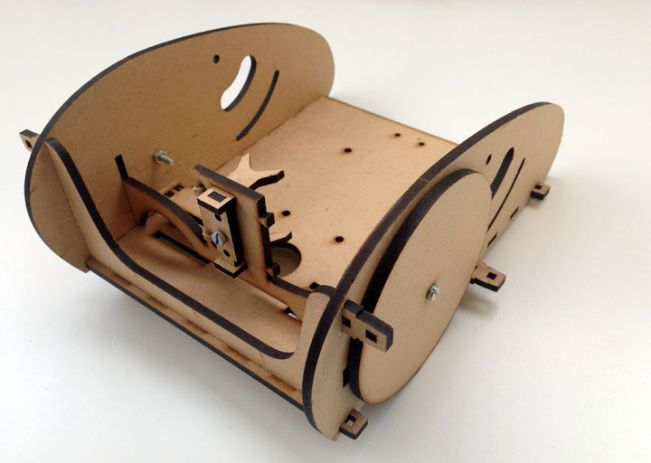
The drive train didn’t work that well but because communications were through USB I couldn’t tell if it was just the drag on the lead or not. I tightened up the holes for the servo and attached the wheels slightly differently but neither worked particularly well.
Version 3
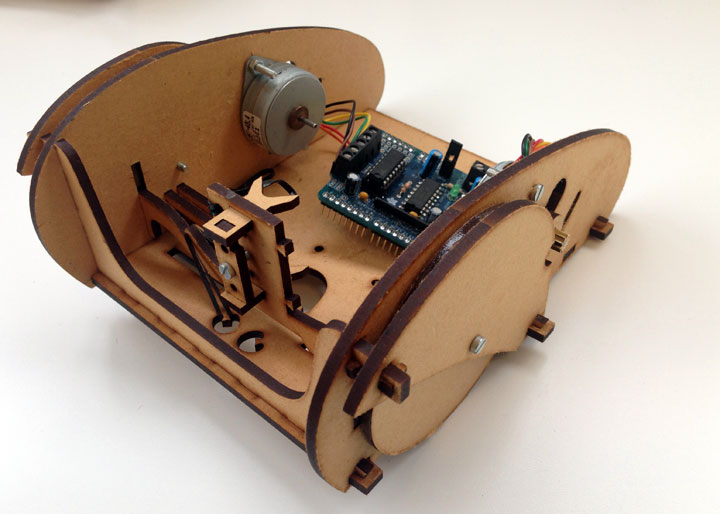
In this design I perfected the servo mount by tying it into the side plane. This is still what’s used in the current iteration. In this version I tried to make the wheels have more grip by applying some silicone around their edges, which should also have solved the problem of grip between the stepper and the wheel. It didn’t. At this point I gave up on this approach of using steppers to drive the wheels from the edge and started looking around for different motors. You can see the Arduino stepper shield that I was using before the custom PCB in this photo.
Version 4
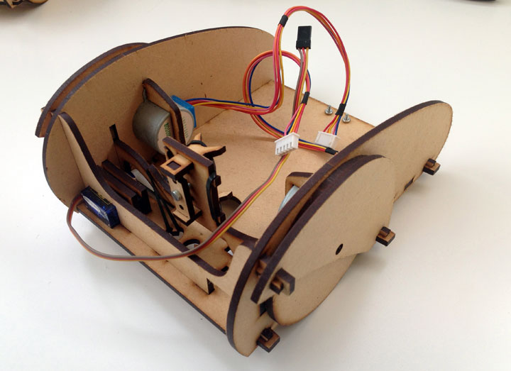
I managed to find a nice, low-cost geared stepper motor which was able to just drive the wheel directly. This eliminated all of the drive train problems, which I’d been becoming increasingly concerned about because of the complexity. Doing this cut out 4 screws and a couple of elastic bands used to tension the motor against the wheel. This is the first version that was able to drive properly and draw a line. The only problem was in the distribution of weight, which was too far back. This caused too much friction on the rear caster wheel and was causing problems with turning.
Version 5
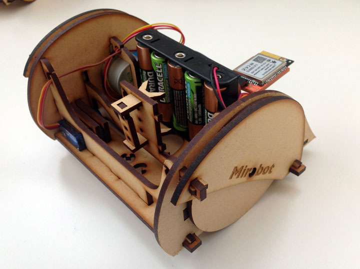
This is the most major change in form factor as it now has a shorter chassis because the battery pack and PCB are now mounted vertically to bring the weight more over the wheels. It also uses a cheaper caster wheel that just clips into the chassis which has also eliminated two screws. It’s now driving well. There’s still a little too much flex in the pen holder which makes it difficult to adjust accurately and tends to make it draw rounded corners slightly so I’m going to attack that next. I also took the opportunity to add a bit of bling with some text on the sides!
That’s us up to date with the current design. It’s been a very gradual evolution from the first design but it’s amazing how much of a difference each tweak makes to the overall functionality.
Read moreWebscale
I spent some time today putting together a simple web page that would allow me to send commands to Mirobot from a web page. I used Blockly to make a Scratch-like gui for composing your commands, then made a quick and dirty WebSocket <-> TCP proxy using Node.js so I could send them direct from the browser. I’m going to put the WebSocket handling into the Arduino eventually, so this is just a quick fix for now. One of the nice things about the WiFi module I’m using is that it has space onboard to embed some web pages, so I’ll be able to make a nice GUI that’s served from the robot itself.
I like the idea of being able to have parity between a few different ways of telling the robot what to do. Here we have a visual programming language which effectively compiles down to Javascript commands, which in turn just send LOGO to the robot. These layers of abstraction provide quite a nice way of gradually being able to expand your knowledge as it’s used for learning. You can see all three in this screenshot:

One of the nice side effects of this is that you can now effectively program the robot in Javascript using the library I made directly, which should open up some really interesting opportunities for hacking and extending it. Websockets are also useful because they don’t have the same cross domain issues that regular HTTP calls would which mean they can be used from anywhere.
Read moreMirobot is alive!
After working on a lot of the component parts of Mirobot in isolation, I decided it was about time to actually make it do what it has been designed to do; draw!
I ran this simple program on it:
REPEAT 5 [
  FORWARD 120
  RIGHT 144
]
Which makes it go forward 120mm and then turn 144 degrees to the right (5 times). That’s the beauty of a simple language like LOGO when it comes to these first steps of learning how to program - it’s very easy to understand what it’s meant to do. This (if you haven’t already run it through in your head) makes it draw a five pointed star. Here’s the proof:
One of the issues I had was that in my initial design for Mirobot I had the battery pack (which is the heaviest part of the robot) towards the back of the chassis near the rear caster wheel as you can see in this photo:
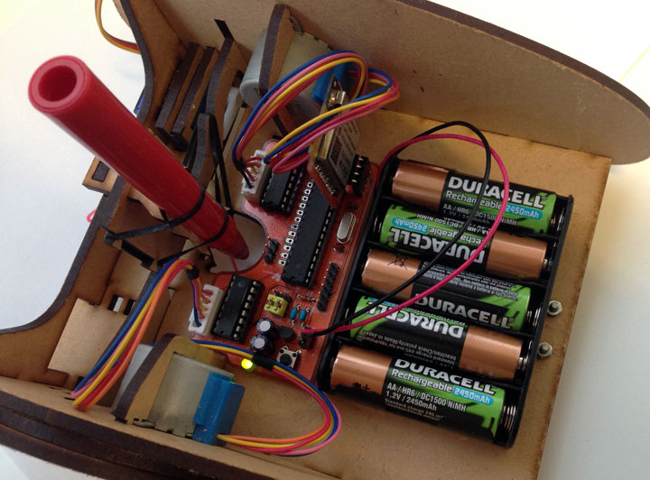
Unfortunately this created too much friction on that wheel which is meant to be free turning. I’ve improved on this by moving the battery upright and as close to the main drive wheels as possible which means they grip better and the caster wheel doesn’t grip as much:
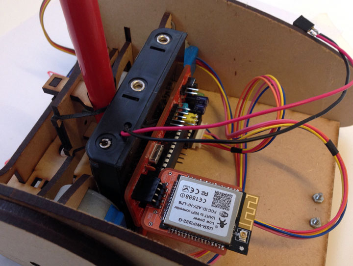
I’m going to get another run of the PCBs done without the nice outline for the pen and designed to slot upright into the chassis base. Should be done in time for Christmas for my kids :-)
Read more


