


Follow these instructions to assemble the Mirobot control board.
The parts
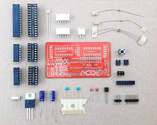
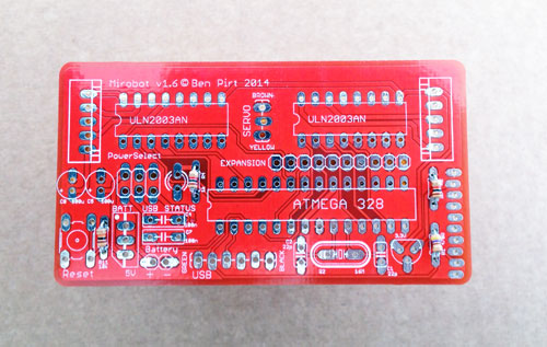
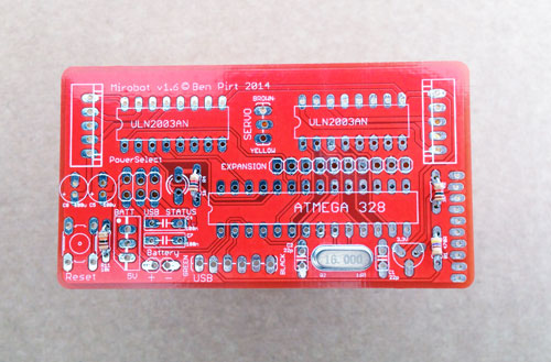
Here are all of the parts that we are going to be soldering. In the centre is the PCB (Printed Circuit Board - make sure you have it this way up) and then clockwise from the top we have:
- Two stepper motor sockets (white)
- The power socket
- The resistors. These are labelled - 10k, 1k and the unlabelled one is 470 Ohm
- The reset switch
- Two power select jumpers
- The 2x3 power select header pins
- The 10 pin WiFi socket
- The 3 pin (for the servo) and 6 pin (for the programming cable) header pins
- The 3.3V voltage regulator
- Two 22uF capacitors
- Two 100nF capacitors
- Two 100uF capacitors
- The 5V voltage regulator
- The crystal
- Two stepper drivers and their sockets
- The Atmega328 and its socket
- The status LED
Step one
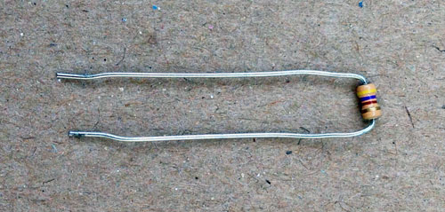
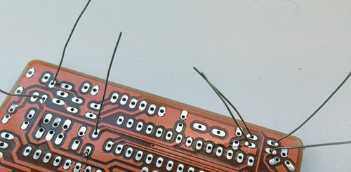
Put the resistors into their holes (bend the wires like in the second picture), solder them in and then snip off the wires that are left sticking out the back of the board. There are three different resistor values and you need to make sure you put the right one in the right place. See the diagram for which is which and what they look like.
Pro-tip: if you bend the wires slightly to either side of the hole like in the third picture they won't fall out when you turn the PCB over.
Step two
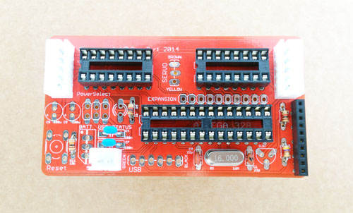
Solder the crystal in place and remove the wire left over after you've soldered it.
Step three
Solder the two capacitors in place either side of the crystal and trim their legs.
Step four
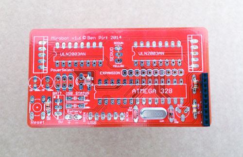
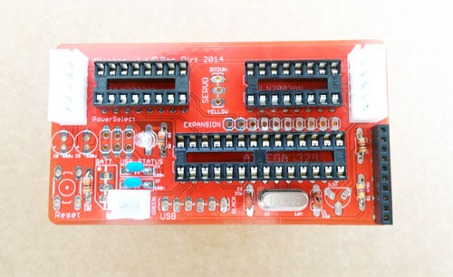
Solder the WiFi socket in place
Step five
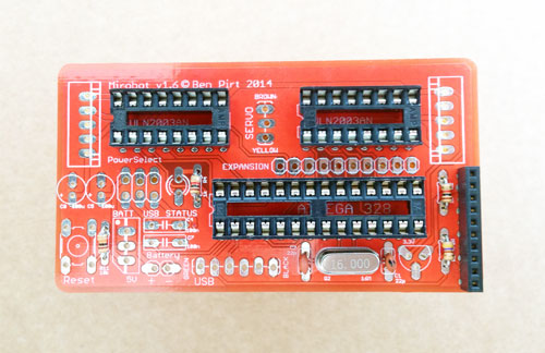
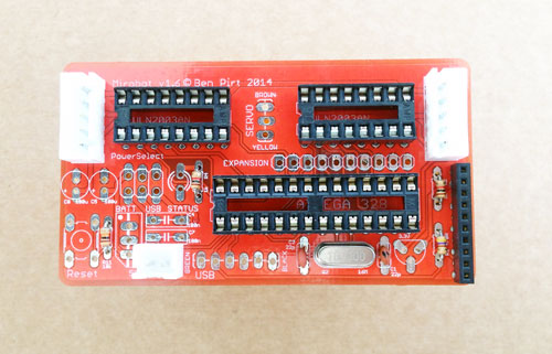
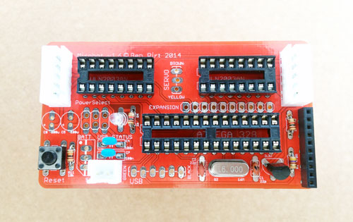
Solder the three chip sockets in place. Note that each one has a small notch on one end - this should line up with the white printing on the PCB and tells you which way the chip should be inserted. All notches on this board should be on the left side like in the photo.
Step six
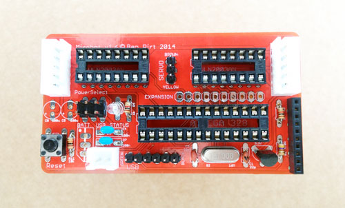
Solder the stepper and power sockets in place. For the two 5 pin stepper motor sockets, you need to make sure that the side with two notches in it is on the inside of the board - check the photo. They should clip satisfyingly into place. The power socket should have the notch facing the edge of the board.
Step seven
Solder the two blue capacitors in place then trim their legs on the back.
Step eight
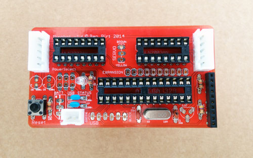
Solder the LED in place. It's important to get this the right way round. The best way to do this is to make sure that the longer of the two legs is in the top hole (make sure the board is the same way around as the photo).
Step nine
Solder the switch. It should clip nicely into place and doesn't need trimming. It should only go in one way round so make sure the pins align before pushing it in.
Step ten
Add the voltage regulator for the WiFi module. You'll need to bend the middle leg back (away from the flat side) slightly to fit in the hole. Make sure you get it the right way round - look at the white shape on the PCB to make sure.
Step eleven
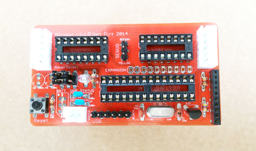
Solder in the header pins. These should hold themselves in place to make it easier to solder. There is one 2x3 set of pins, one 1x6 set and one 1x3 set. These should be inserted with the small end of the pins going through the PCB from the top down.
Step twelve
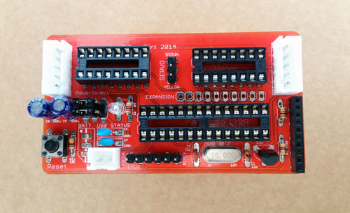
Put the jumpers on to the 2x3 header pins you just soldered on. Depending one which side they are placed they will let you power the robot from battery (left) or from USB (right). For normal operation they should go on the left two pins horizontally (check the photo).
Step thirteen
Solder in the two larger, round capacitors and trim their legs. These need to be put in the right way round. The long leg of the capacitor should go into the bottom hole on the board that has the + symbol next to it. The white stripe on the capacitor should be facing towards the white socket for the stepper motor.
Step fourteen
Solder in the three legged voltage regulator and trim its legs. This also needs to go in the right way round. The flat metal side with the hole in it should be on the right hand side like in the picture.
Step fifteen
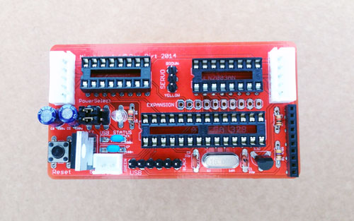
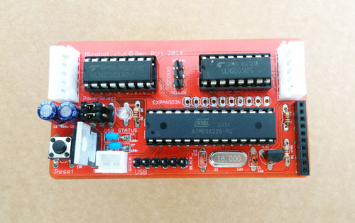
Put the chips into their sockets. It is very important to make sure that the small notch on the end of the black body of the chip points matches up with the notch on the socket. In this picture they are all on the left side.
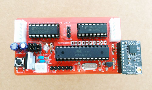
Step sixteen
Plug the WiFi module into the main board.
Next steps
First, inspect your soldering. There should be no messy bits of solder bridging from the pins to other parts of the PCB. If there are, use the soldering iron to remove them. Then:
- Put 5 AA batteries into the battery pack and then plug it into the PCB.
- The green light should flash for a few seconds and then go solid. If there is no green light, then check all of the components are in the right way round and there are no other mistakes.
- If the green light is flashing then the board is OK and you should plug in the servo, making sure the colours on the cable match with the words on the board. This will align the servo to the up position, ready for building the chassis.
- Now you should build the chassis