


Follow these instructions to build the Mirobot chassis.
The parts
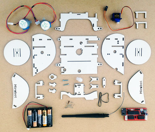
You should already have soldered together the PCB. Now it's time to put the chassis together. Here are all of the parts that you'll need. From left to right, top to bottom we have:
- Two stepper motors
- The bulkhead
- The servo
- Two servo mounts
- Wheel
- Left side plate
- Base
- Right side plate
- Wheel
- Left wheel cover
- Left stepper mount
- The antenna mount (three small pieces)
- The pen arm screws
- The pen arm
- The rear plastic caster wheel
- The two pen holders
- The pen adjustment plate
- Two elastic bands
- Right stepper mount
- Right wheel cover
- Battery holder
- The small pegs
- WiFi antenna
- The main PCB
One useful thing to bear in mind is that the white faces of all of the pieces generally face forward.
Step one
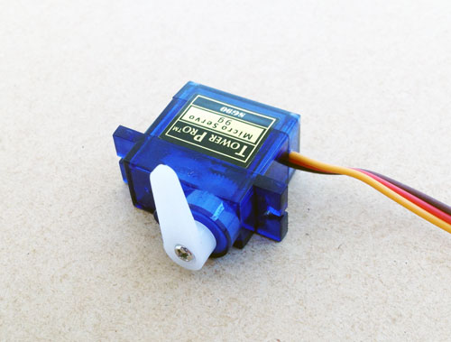
You should already have powered up the servo at the end of the PCB build instructions which gets it into the correct "up" position. Attach the one sided lever to the servo as shown and screw it on with the small screw. Make sure it is aligned exactly like in the picture.
Step two
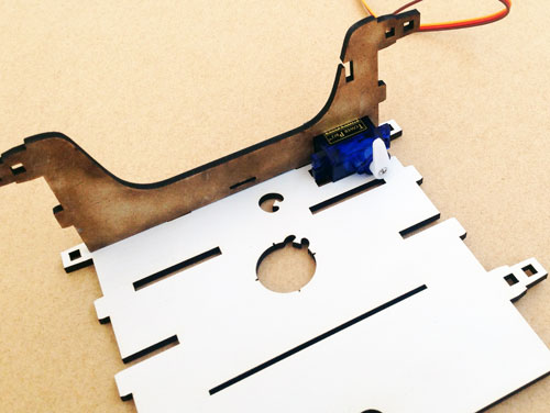
Place the blue servo on the chassis base with its cable to the edge and slot the bulkhead over the top.
Step three
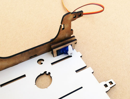
Add the two U shaped servo mounts over the servo on either side of the plastic plates. They should slot into the holes on the base.
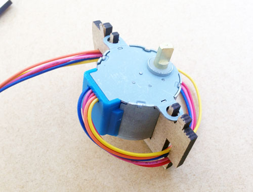
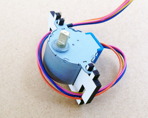
Step four
Find the left stepper motor bracket and put the motor into it as shown in the picture. Make sure that the bracket goes through the two screw holes on the motor. Wind the cable once around it which will help keep the cable tidy but also helps to stop it falling out while you're building it. The cable should go through the bottom hole first, then loop around the motor and go through the top hole.
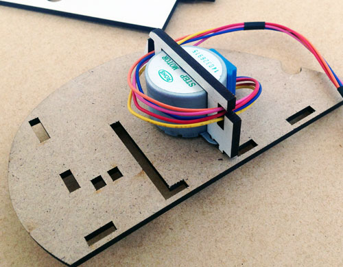
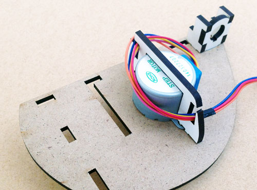
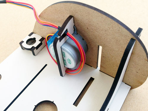
Step five
Sit the motor in its bracket onto the chassis base, making sure that the blue part is facing the back of the robot.
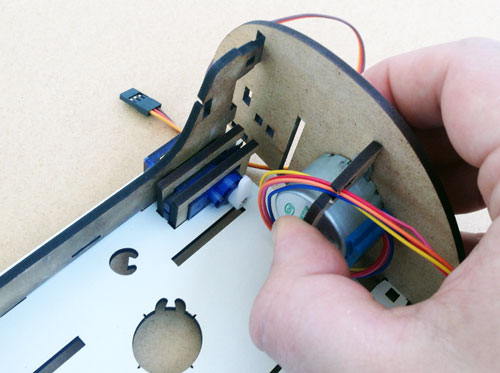
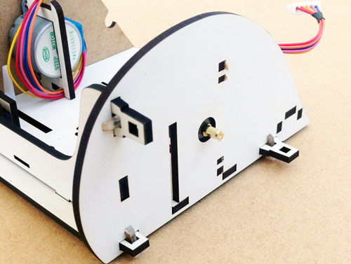
Step six
Gently slide the side of the robot on, taking care to align it with all of the pieces sticking through it. This can sometimes get stuck - don't force it on. If it's not going on easily, make sure that all of the pieces are properly aligned with the holes.
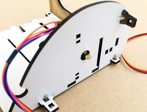
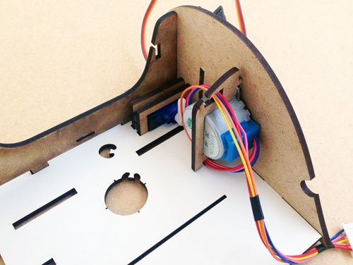
Step seven
Take three of the small pegs and push them through the small holes against the side of the robot. They should push through so that you can see the peg on either side of the hole. It is best to push the two bottom pegs in from the bottom up, otherwise they can push out when you pick up the robot. It can be helpful to use something hard to push them in to make sure they hold properly.
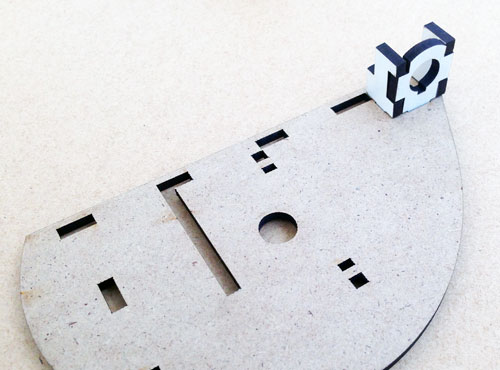
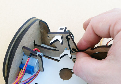
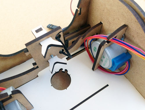
Step eight
Push the antenna mount in to the left side plate as shown in the picture. This can be a little fiddy.
Step nine
Place the second stepper motor in the right side bracket as shown. Wind the cable around in the same way as the first motor.
Step ten
Sit the stepper motor in its bracket on to the left side plate as shown.
Step eleven
Slide the side on to the robot as you did on the other side.
Step twelve
Peg it on with the three pegs the same as you did for the other side.
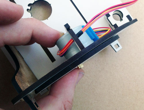
Step thirteen
Clip both wheels on to the metal part of the stepper motor, making sure to align them correctly. It should be a reasonably tight fit. It is best to squeeze together with your thumb on the back of the motor and your finger on the wheel as shown in the first picture.
Step fourteen
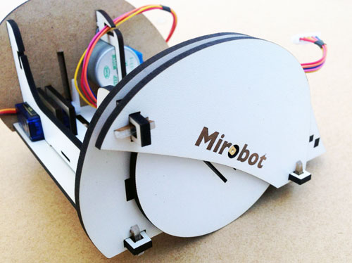
Slide the wheel covers on to the tabs so that they cover the wheels then peg them on. There are two pieces like this and they will only go on one way with the logo facing the outside.
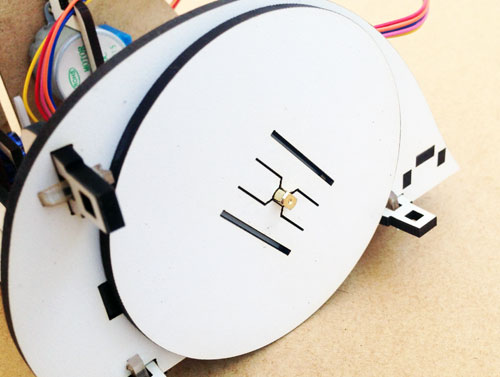
Step fifteen
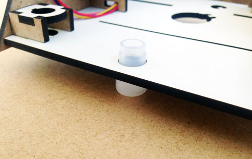
Push the white plasic caster wheel through the hole in the back. Don't push directly on to the ball as this can damage it, push using the ridge around it.
Step sixteen
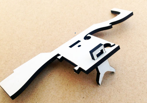
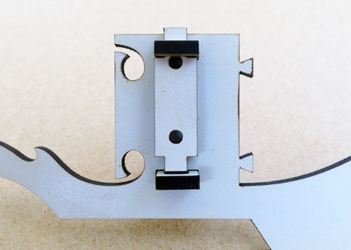
Put the main part of the robot to one side now and find the pieces for the pen arm as shown in the photo.
Push the top pen mount through the pen arm as shown in the photo, making sure that it is facing the right way.
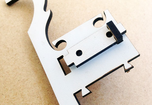
Step seventeen
Push the long end of the adjustment plate (that has two holes in it) up through the hole in the pen mount as shown in the photo.
Step eighteen
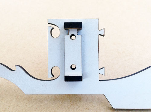
Push the second pen mount through the pen arm pointing in the same direction as the first.
Step nineteen
Slide the adjustment plate down into the second pen mount that you just put in.
Step twenty
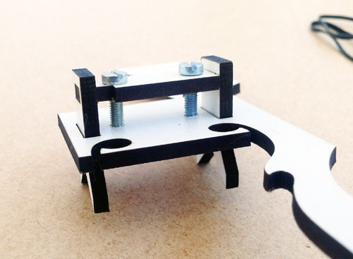
Place the two screws through holes in the bracket and screw them both in by the same amount.
Step twenty-one
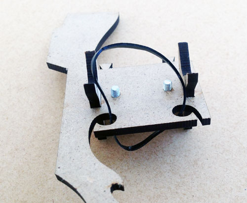
Hook the elastic band through the holes and around the small pegs on the other side. You can hook the elastic on to the pen mounts to keep it tight until you put a pen in place.
Step twenty-two
Slide one end of the pen arm into the slots in the main chassis, with the pen mounts facing inwards towards the hole in the base. Drop the other end down into place so that it sits in nicely.
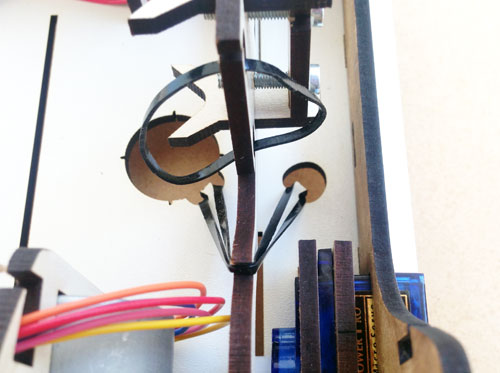
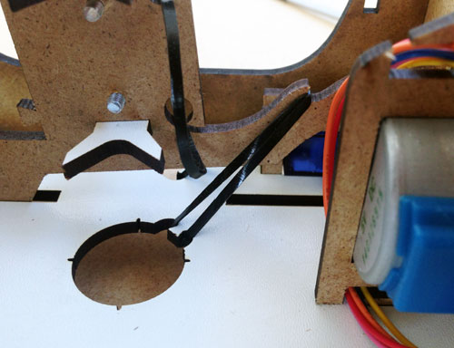
Step twenty-three
This is the fiddliest part of the assembly. You need to hook the elastic band over the arm so that it is held in place. The technique I use to do this is:
- From below, push the elasic band through the smaller hole at the front, hooking it over the small peg
- Hold one finger over the bottom to keep it in place
- Stretch it over the arm, making sure it is in the notch on the arm
- Stretch it and push it through the big pen hole and use the screwdriver to hook it on to the second peg
Step twenty-four
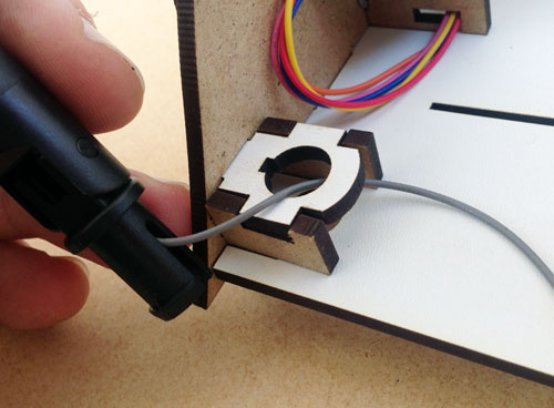
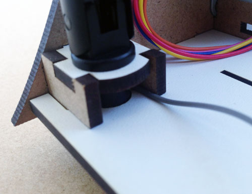
Fit the antenna. Again, this is a little tricky but is OK if you follow this technique:
- First thread the cable through the hole and then out of the side as shown in the picture
- Make sure the cable passes through one of the slots in the base of the antenna (see picture)
- Push the base through the holes, making sure not to trap the cable
- Make sure the notch aligns properly
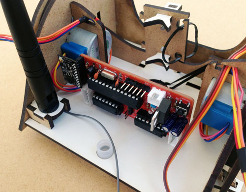
Step twenty-five
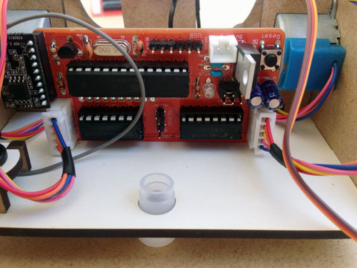
Fit the PCB into the slot. It should go in upside down with the white stepper sockets at the bottom.
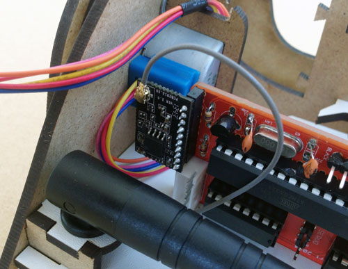
Step twenty-six
Click the small connector on the end of the antenna cable on to the small circular socket on the WiFi module. It's fiddly, but just get it aligned properly and push it in. It can help to put the antenna down out of the way.
Step twenty-seven
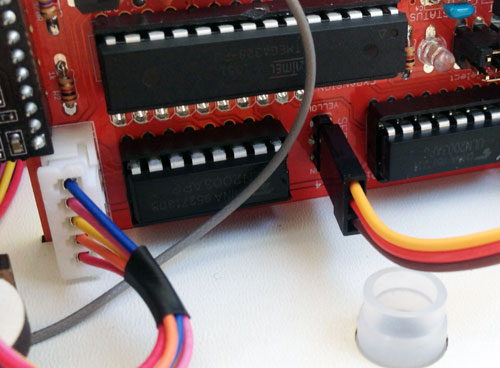
Connect both stepper motors. The plugs should only be able to go in one way.
Step twenty-eight
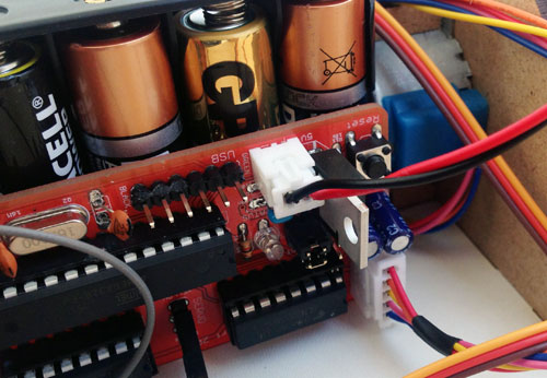
Connect the servo with the yellow cable at the top.
Step twenty-nine
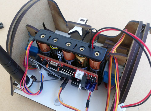
Put in the batteries and slide the battery holder down between the two stepper motors.
Step thirty
Once you're ready to use Mirobot you can connect the power from the battery holder to the power connector.
Well done! You're ready to start using Mirobot