


Follow these instructions to assemble the Mirobot control board.
Unwrapping
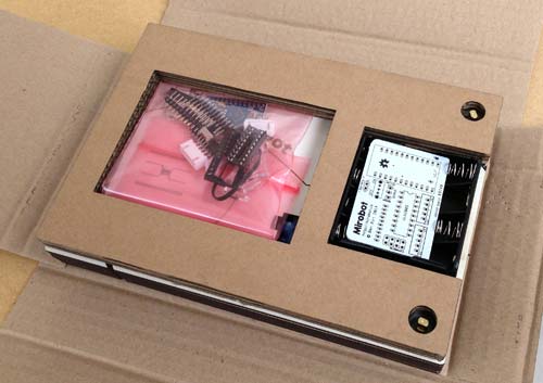
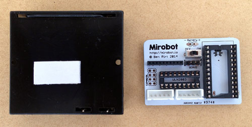
When you unwrap the package you should see a pink bag with the components in it, a white PCB and the black battery box.
Take these out and put the rest of the package to one side for now.
To assemble the PCB you will need:
- A soldering iron
- Solder (60/40 tin/lead solder is the easiest to use. Lead free is harder)
It is highly recommended to watch this soldering tutorial before starting if you're not used to soldering. Soldering isn't too difficult, but it's worth taking the time to make sure it's done well so it is more likely to work first time.
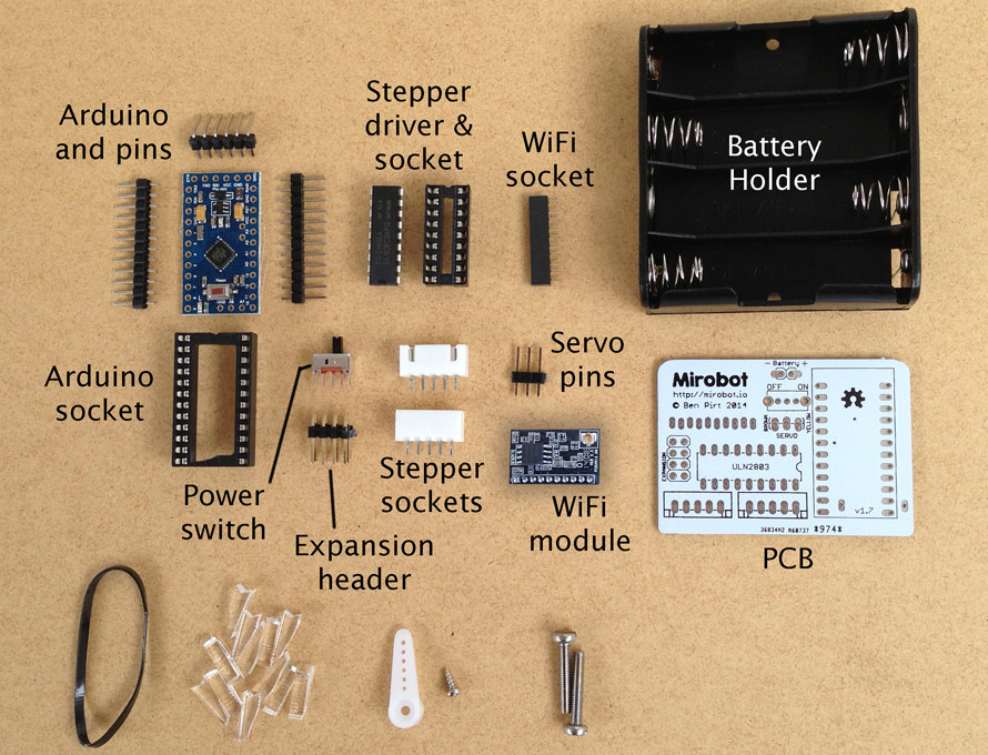
The parts
Here are all of the parts that are in the pink bag. At the bottom of the picture are the parts for assembling the chassis so put these back in the bag for now.
Step one
Solder the WiFi socket in place.
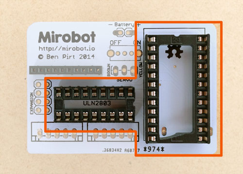
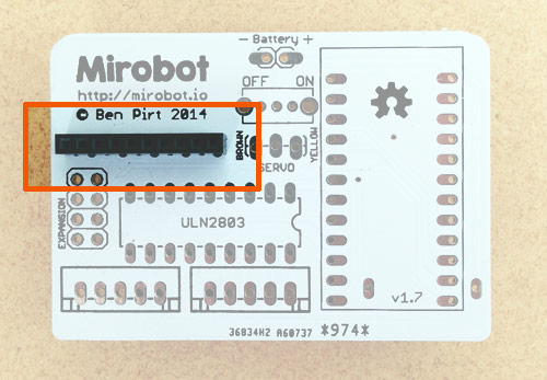
Step two
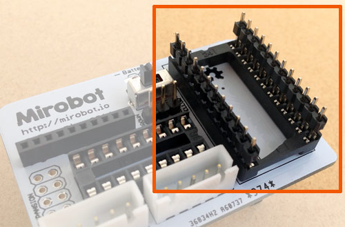
Solder both of the chip sockets in to place. Take care to put the notch in the smaller one in line with the outline on the PCB. The larger one should have the notch on the top otherwise you won't be able to solder a later step.
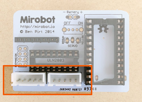
Step three
Solder the stepper sockets in place. You need to make sure that the side with two notches in it is at the edge of the board - check the photo. They should clip satisfyingly into place.
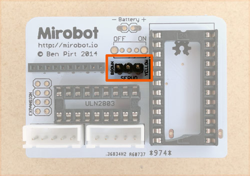
Step four
Solder the three servo connector pins. This should be inserted with the small end of the pins going through the PCB from the top down.
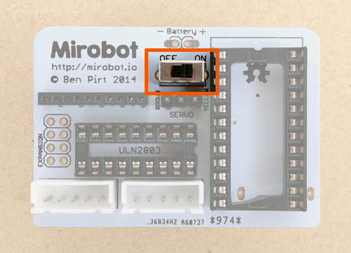
Step five
Solder in the power switch.
Step six (optional)
Solder in the expansion pins. If you're not planning on using any expansion kits you don't need to do this, though it won't harm to put them in anyway and it's good practice soldering!
Step seven
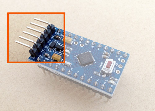
Now we need to solder the pins on to the Arduino board we are using. The best way of doing this is to push both rows of pins into the Arduino socket as shown in this photo.
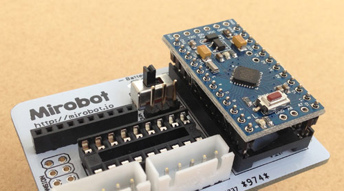
You can then put the Arduino onto these pins and solder them in. Doing it this way makes sure they are well aligned and will fit in and out nice and easily. The pins are quite small but take your time and it shouldn't be too tricky.
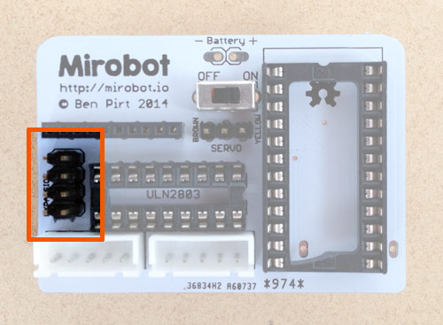
Step eight (optional)
If you think you might want to reprogram the Arduino at some point in the future, you can solder on the programming pins as shown in the photo. You don't need these on in order to use Mirobot though.
Step nine
First, inspect your soldering. There should be no messy bits of solder bridging from the pins to other parts of the PCB. If there are, use the soldering iron to remove them. We're going to test the board before soldering the battery pack on because once it's in place it would need removing if there are any errors:
- Move the switch to the Off position.
- Put the Arduino and the WiFi module in to their sockets
- Put 4 AA batteries into the battery pack.
- Put the battery pack pins into the two remaining holes on the board, like in this photo
- Push gently on the bottom of the battery pack so it makes contact with the holes
- Move the switch to the On position.
- There should be two LEDs lit up on the Arduino. One should stay solid (the power LED) and one should flash for a few seconds before turning solid as well.
If the LEDs don't turn on then turn it off straight away because there's most likely a short circuit. Take a careful look at the back of your board to double check for any bits of solder that might be bridging between pins.
Don't solder the battery pack on until you have successfully done this step!
Step ten
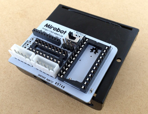
It's time to attach the battery holder. First, peel off the cover over the sticky pad on the battery holder. Then push the pins on the holder through the PCB from behind like in this picture. Once you've pushed it on so it sticks then you should carefuly solder it making sure you don't melt the Arduino socket.
Put the batteries in the holder and turn the switch on again to make sure the LEDs still come on and flash correctly. If the LED starts flashing then the board is OK and you should plug in the servo, making sure the colours on the cable match with the words on the board. This will align the servo to the up position, ready for building the chassis.
Now you should build the chassis