


Follow these instructions to assemble the Mirobot control board.
Step one
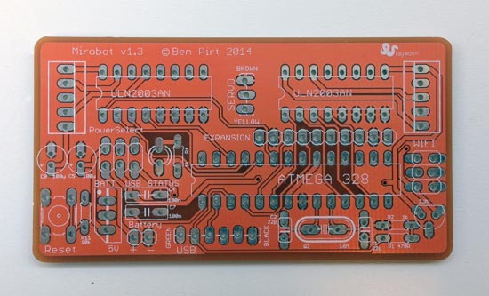
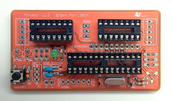
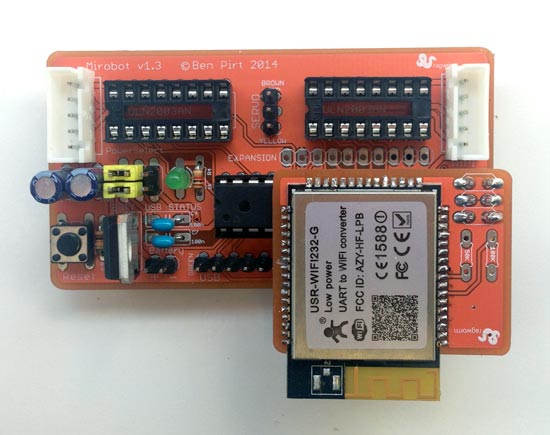
Here's the main PCB we're going to be soldering first.

Step two
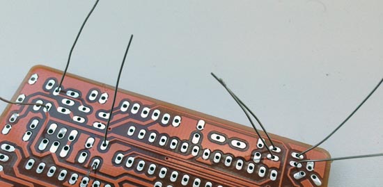
Put the resistors into their holes, solder them in and then snip off the wires that are left sticking out the back of the board. There are three different resistor values and you need to make sure you put the right one in the right place. See the diagram for which is which and what they look like.
Pro-tip: if you bend the wires slightly to either side of the hole like in the second photo they won't fall out when you turn the PCB over.

Step three
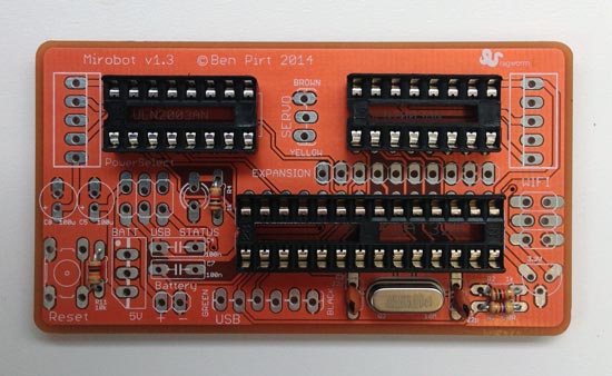
Solder the crystal in place and remove the wire left over after you've soldered it.

Step four
Solder the two capacitors in place either side of the crystal and trim their legs.
Step five
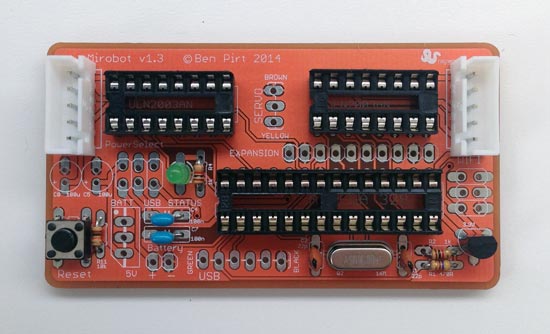
Solder the three chip sockets in place. Note that each one has a small notch on one end - this should line up with the white printing on the PCB and tells you which way the chip should be inserted. All notches on this board should be on the left side like in the photo.
Step six
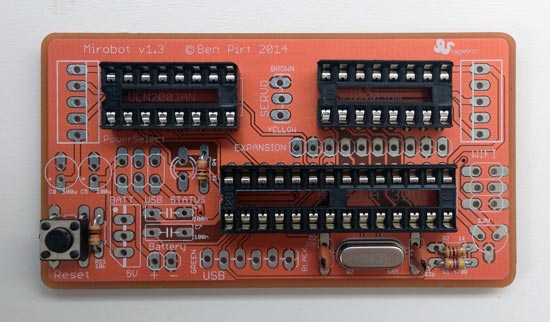
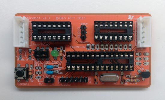
Solder the switch. It should clip nicely into place and doesn't need trimming.

Step seven
Solder the two blue capacitors in place then trim their legs on the back.
Step eight
Solder the LED in place. It's important to get this the right way round. The best way to do this is to make sure that the longer of the two legs is in the top hole (make sure the board is the same way around as the photo).

Step nine
Add the voltage regulator for the WiFi module. You'll need to bend the middle leg back slightly to fit in the hole. Make sure you get it the right way round - look at the white shape on the PCB to make sure.
Step ten
Solder in the white plugs for the stepper motors. You need to make sure that the side with two notches in it is on the inside of the board - check the photo.
Step eleven
Solder in the header pins. These should hold themselves in place to make it easier to solder.

Step twelve
Solder in the socket for the WiFi module.

Step thirteen
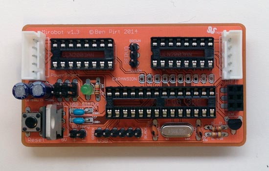
Solder in the two larger, round capacitors and trim their legs. These need to be put in the right way round. The long leg of the capacitor should go into the bottom hole on the board that has the + symbol next to it. The white stripe on the capacitor shoul dbe facing towards the white socket for the stepper motor.
Step fourteen
Solder in the three legged voltage regulator and trim its legs. This also needs to go in the right way round. The flat metal side with the hole in it should be on the right hand side like in the picture.

Step fifteen
Solder in the header pins to the WiFi module. Make sure they are on the side without the module mounted on it as in the photo.
Step sixteen
Plug the WiFi module into the main board. If you've already assembled the chassis then you're ready to connect everything up and start using Mirobot.