


Follow these instructions to build the Mirobot chassis.
Step one
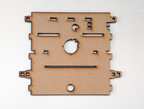
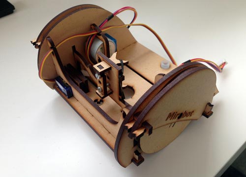
Lay the chassis base on the table like this. The edge with three slots in is the front and the one with the circle is the back.

Step two
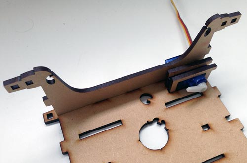
Place the blue servo on the chassis base with its cable to the edge and slot the two U shaped brackets over the top on either side of the flat bits on either side.
Step three
Place the cross member across the front of the chassis so that the rectangular hole in it goes over the servo.
Step four
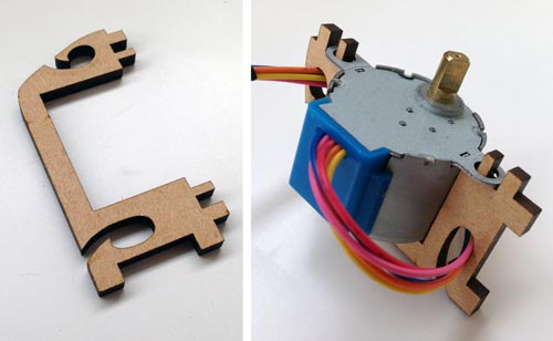
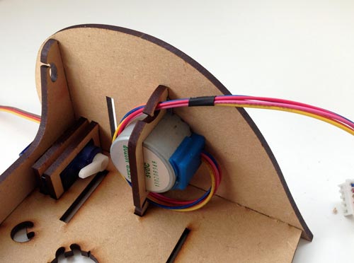
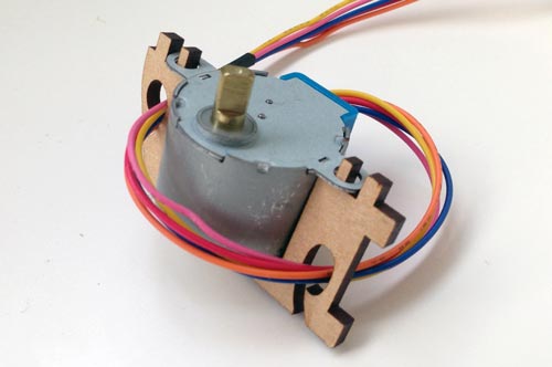
Find the stepper motor bracket and put the motor into it as shown in the picture. Make sure that the bracket goes through the two screw holes on the motor. Wind the cable once around it which will help keep the cable tidy but also helps to stop it falling out while you're building it. The cable should go through the bottom hole first, then loop around the motor and go through the top hole.
Step five
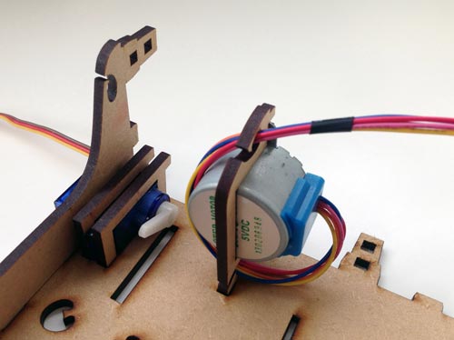
Sit the motor in its bracket onto the chassis base, making sure that the blue part is facing the back of the robot.
Step six
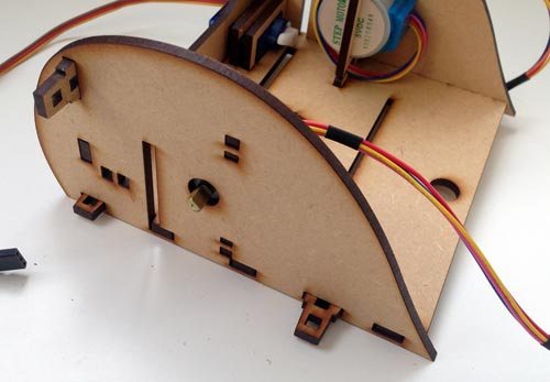
Gently slide the side of the robot on, taking care to align it with all of the pieces sticking through it. This can sometimes get stuck - don't force it on. If it's not going on easily, make sure that all of the pieces are properly aligned with the holes.

Step seven
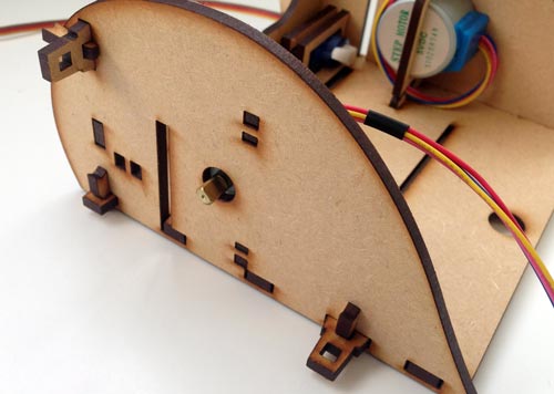
Take three of the small pegs and push them through the small holes against the side of the robot. They should push through so that you can see the peg on either side of the hole.
Step eight
Place the second stepper motor in its bracket as shown. Wind the cable around in the same way as the first motor.

Step nine
Sit the stepper motor in its bracket on to the chassis base as shown.
Step ten
Slide the side on to the robot as you did on the other side.
Step eleven
Peg it on with the three pegs the same as before.
Step twelve
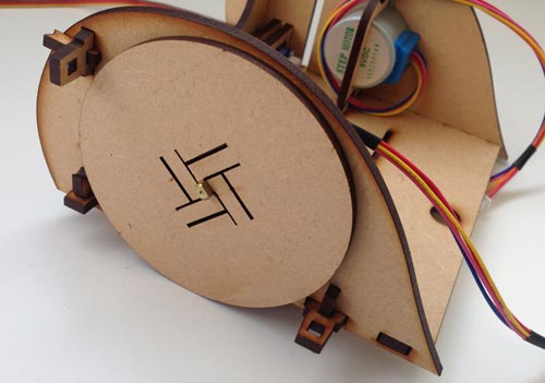
Clip both wheels on to the metal part of the stepper motor, making sure to align them correctly. It should be a reasonably tight fit and you may mneed to nudge the centre of the wheel apart slightly to get it on.
Step thirteen
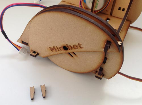
Slide the wheel covers on to the tabs so that they cover the wheels then peg them on. There are two pieces like this and they will only go on one way with the logo facing the outside.

Step fourteen
Put the main part of the robot to one side now and find the pieces for the pen arm as shown in the photo.

Step fifteen
Push one of the pen mounts through the pen arm as shown in the photo, making sure that it is facing the right way.
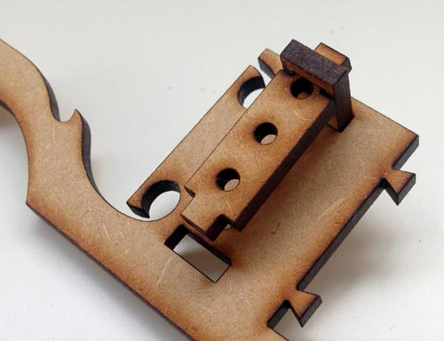
Step sixteen
Push the long side of the small bracket (that has three holes in it) up through the hole in the pen mount as shown in the photo.
Step seventeen
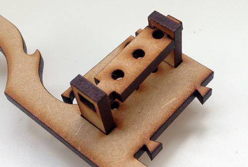
Push the second pen mount through the pen arm pointing in the same direction as the first.

Step eighteen
Slide the bracket with three holes down into the second pen mount that you just put in.
Step nineteen
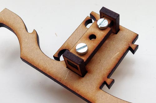
Place the two screws through the first and third holes in the bracket and screw them both in the same amount.
Step twenty
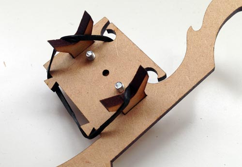
Hook the elastic band through the holes ond around the small pegs on the other side. You can hook the elastic on to the pen mounts to keep it tight until you put a pen in place.

Step twenty-one
Slide one end of the pen arm into the slots in the main chassis, with the pen mounts facing inwards towards the hole in the base. Drop the other end down into place so that it sits in nicely.
Step twenty-two
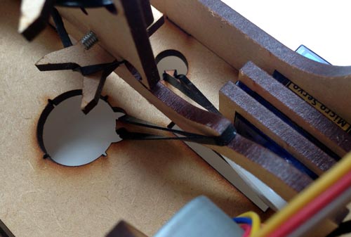
This is the fiddliest part of the assembly. You need to hook the elastic band over the arm so that it is held in place. The technique I use to do this is:
- From below, push the elasic band through the smaller hole at the front, hooking it over the small peg
- Hold one finger over the bottom to keep it in place
- Stretch it over the arm, making sure it is in the notch on the arm
- Stretch it and push it through the big pen hole and use the screwdriver to hook it on to the second peg
Step twenty-three
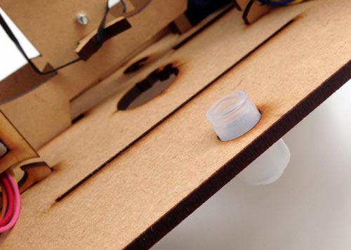
Push the white plasic caster wheel through the hole in the back. Don't push directly on to the ball as this can damage it, push using the ridge around it.
You're done!
Once you've soldered the PCB, you can connect everything together and start using Mirobot!