The First Milestone
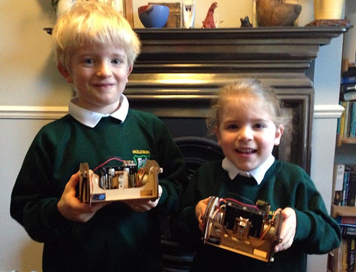
The main reason I started designing Mirobot was to be able to build it with my kids so Christmas seemed like the perfect opportunity to do this.

The things you learn from doing real user testing are fantastic. They both assembled the chassis and managed to solder the circuit board mostly by themselves. Obviously there was a lot of adult supervision but they both seemed to really enjoy the process of actually building something for Christmas, not just getting it out of a box. The easier it is to build, the more likely people are to use it and recommend it to others, so I’ll be designing out some of the points of friction I we came across to make it easier to build. Audrey is keen to do some more soldering on the next version. The learning points were:
- The WiFi module was a bit wobbly on the connector I was using. Not sure if this actually caused any issues but I didn’t like it
- Some of the smaller pads on the PCB were difficult to solder. They managed fine with all of the larger pads, so I’m going to make them all this size
- It was quite easy to short between the pads and the solder resisted ground plane so I’m going to increase the separation between them
- The reception of the WiFi module using the built-in antenna was not too great - might need to provide it with an external antenna
- The servo for the pen arm wasn’t very well aligned. Need to check the measurements to see if one of the cutting holes has been shifted slightly
- The fact that the chassis construction is symmetrical means that the servo can be placed at either side. This was intentional but I think it only confuses things because you’d have to use slightly different firmware
- It needs a status indicator so you can see that it’s happy. At the moment there’s a basic power LED, but I think I’m going to drive this from the Arduino so that you can also tell whether the WiFi is connected and the program is running happily
- The PCB is hard to debug once you’ve built the whole thing. This is the same for any PCB really, but I think if I write the instructions so that you check it as you go along it will be much easier to isolate where the short might be
- Pressing the reset button for the Arduino should also reset the WIFi module - I’ll need to bring this line out through the connector to the module
- The small pegs were fiddly and it was hard to tell which way round they should go - I can make them a bit bigger so there’s more to grab on to and they are more obvious
- The wheel attachment is a bit loose and needs tightening a bit more
- The battery holder feels a bit loose as it’s just resting there between the steppers and the PCB. I’d like this to feel a bit more solid
However, fundamentally, the robot worked - they were able to assemble and solder it themselves and then we were able to make it draw some patterns which they thought was “awesome” and “epic”. I was a little concerned before Christmas about how they would handle the soldering, but they did a great job.
What’s next?
I’m going to revise things based on this list of improvements and make the whole thing a bit more stable then I’ve got some ideas for some cool projects to show off its capabilities, particularly around the fact that it’s internet accessible. Once I’ve done that I think it’s probably time to start thinking about Kickstarting it to see if anyone else wants one. I’d love to get it into some schools so that more kids can get some experience building and programming it. If you’d like me to keep you posted on when you can get hold of one then sign up to the mailing list below.


